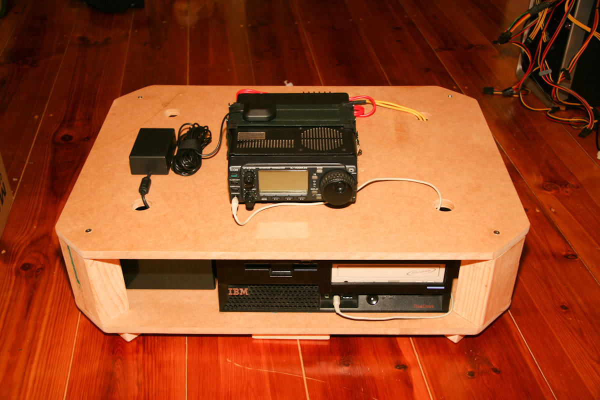
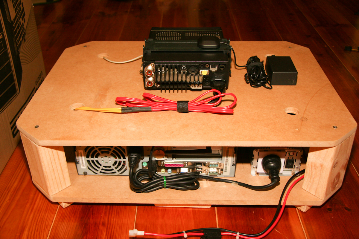
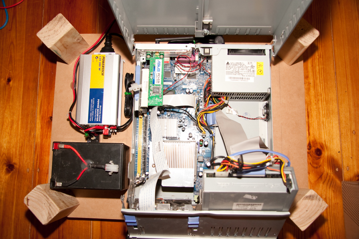
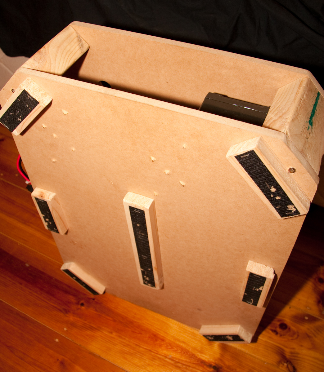
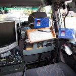
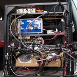
Birth of a carputer
I've put together a simple carputer to handle the balloon tracking and map plotting automatically. It's essentially a smallish desktop running from an inverter, with a backup battery & diode block to let me start the car without rebooting the PC.
The Icom 706MKIIG is controlled by the PC for automatic tuning & tracking - there's also a GPS module onboard, a 3G internet connection, and an ad-hoc wifi network broadcast, allowing me to control the lot from my netbook. Velcro straps keep the whole thing from sliding around in my boot.
More info soon, pics below!
Launch of Horus 2
On Monday the 8th of March we launched Horus 2 - the weather was very poor, and combined with other factors, this resulted in a less than satisfactory launch. Once we'd waited for a break in the wind & rain to let the balloon go, we realized that it was underfilled & didn't have the lift we'd wanted - the balloon was only ascending at 1m/s. With the high winds, the balloon was moving faster than we could keep up.
Within 45 minutes, we realized the balloon had stopped ascending (at around 1500m) & was coming down very slowly - and still racing away from us at 80km/h. Fortunately, thanks to those listening in & some contact via the local repeaters, we still had a good idea where it was and we kept chasing it - eventually recovering it in a tree with the balloon still inflated here.
It looks as though the polystyrene payload and parachute absorbed enough water in the rain to negate the small amount of lift provided by the balloon, and the payload slowly came down, where it was dragged along the ground by the wind for some time, until it wound up in a tree.
Given the balloon didn't reach the minimum altitude for the higher baud rates to kick in (5km), the launch was not a great success - though it was certainly a learning experience for us, and we wont be making the same mistakes next time.
I apologize to everybody who tuned in to help us track the payload or helped out in some other way for the rather disappointing launch.
I'm planning on re-launching the same payload soon with a few improvements - will keep the blog updated!
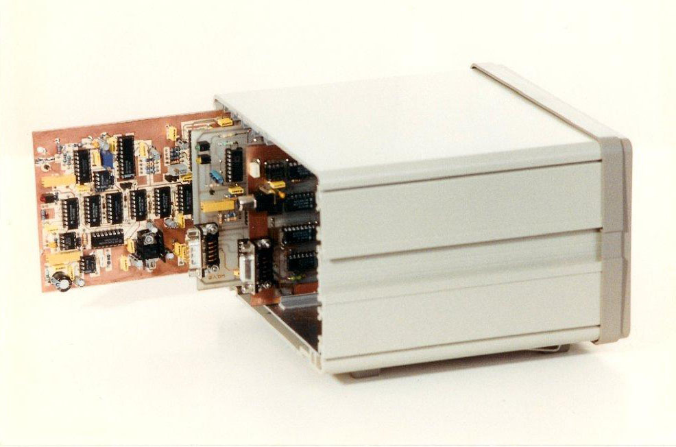
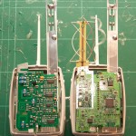
In other news, my boards have arrived from BatchPCB, and I've put together the first prototype of my Isis flight computer. Testing is looking very positive so far - the FSA03 Ublox 5 module is excellent.

Isis v1.0
Backup CW beacon
I put together a simple backup CW (morse code) beacon for future launches yesterday for total cost of only a few dollars.
The beacon is comprised of only a microcontroller, a $4 10mW 434mhz transmitter & a few passives. The beacon is a standalone device, and pips out a few bits of information about the payload, including the frequency and transmission mode for the primary telemetry, how long the beacon has been switched on for and a URL to the project web page.

Backup CW Beacon
Because of the simplicity of the transmitter, it has very poor thermal stability, and is very easily affected by objects touching it/in close proximity to it (affecting the loading of the crystal - it's very cheap!). It won't be of much use whilst the balloon is in the air, but if we lose the payload, this should help us find it once it's on the ground.

Backup CW beacon
Running on 2AA lithium batteries, run time should be close to a week when constantly transmitting, more if the duty cycle is lowered a bit.
Edit: I have uploaded both the schematic & board layout. ![]()
Future launches
The blog has been quiet since launch due to catching up with real world commitments - thanks to all who have emailed me recently to congratulate us on the launch! ![]()
I am planning on launching more balloons, and have been experimenting with options for flight computers - whilst the Arduino was great, it was somewhat limited by its form factor - ideally future launches will carry a custom flight computer with GPS, radio & SD logging all on the one board.
I have been working on the design of such a board - here's a picture of the current design:

Isis flight computer
The board is based around 2 ATmega 328P microcontrollers - one acting as the core of the flight computer, the other dedicated to handling telemetry. This will allow the radio telemetry to be offloaded from the core, meaning more can be done whilst the lengthy RTTY transmission takes place.
I've switched from the Lassen IQ GPS module to the Falcom FSA03, which I sourced from Esawdust. This module is far more sensitive than the Lassen, and also features the Sarantel helical antenna, which performs in most any orientation. The module is also capable of providing fix data at 4hz.
The Radiometrix NTX2 25mW transmitter is also present on the board, as is the SD card used for logging. I've also included indicator lights to make launch & setup much easier. The board has a DIL header providing connections to system voltages & data pins on the core for connecting daughterboards which will house additional sensors/equipment.
With the radio offloaded to a dedicated processor, the board will be able to log position, temperature, pressure, humidity much more frequently - resulting in better data at the end of the day.
I've also been experimenting with PCB production - I bought myself a Dremel drill press & some 0.8mm tungsten carbide drill bits, and have whipped up some simple test boards - given that I'd never tried etching PCB's at home, I was rather happy with the results on my first board, an ATmega 328P protoboard whipped up in a couple of hours.

ATmega protoboard
I'm looking at having the main board commercially produced, and will likely hand-etch the daughterboards to go with it.
As for future launches - I plan to launch the original flight computer at least once more, likely quite soon. I'll be experimenting with a few ideas in future launches: higher baud rates, coding (error correction) & eventually bi-directional communication.
Look out for more soon! ![]()
RDF, balloon chasing more updates
A rather large update this time!
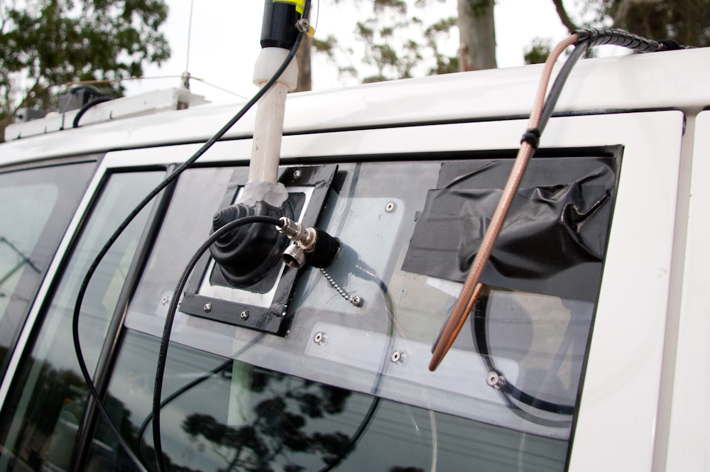
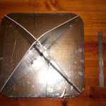
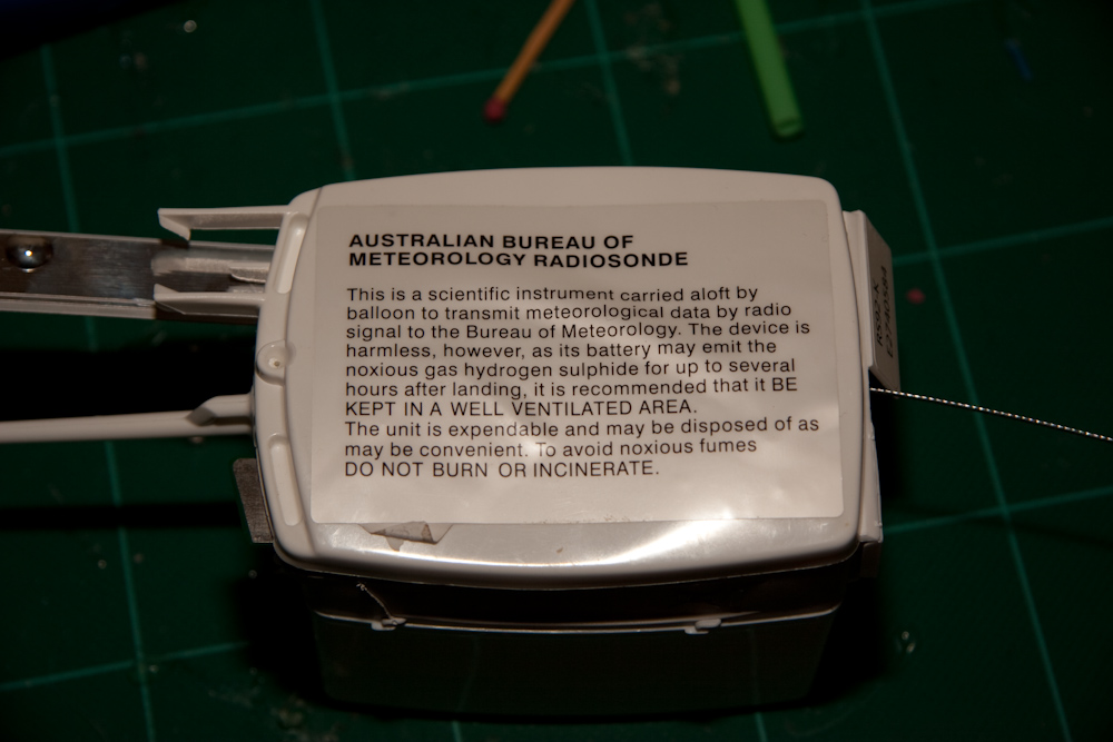
I recently caught up with one of the many hams who have emailed me (thanks everybody!) regarding the project - Adrian, VK5ZSN. Adrian has lots of experience in chasing BOM sounding balloons, and has recovered many of them in the past. As well as invaluable input & assistance, Adrian has given me a bunch of stuff for the project - including radar reflectors and radiosondes. He's also offered to test my yagi on a network analyzer so I can work out if it's performing as well as it could be.
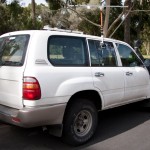
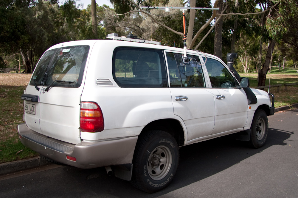
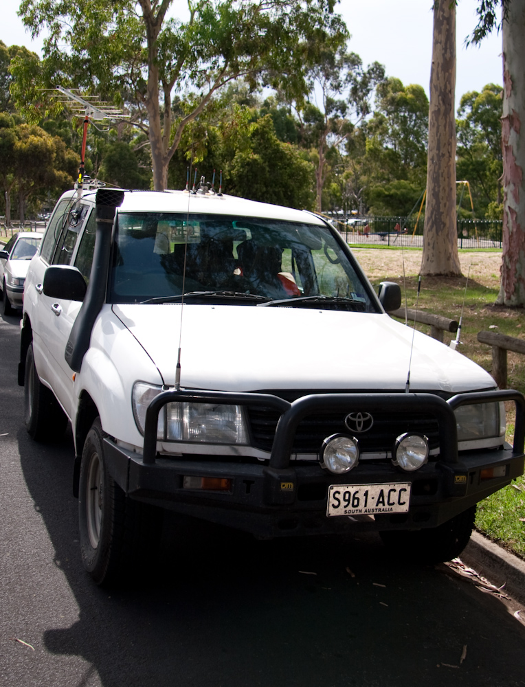
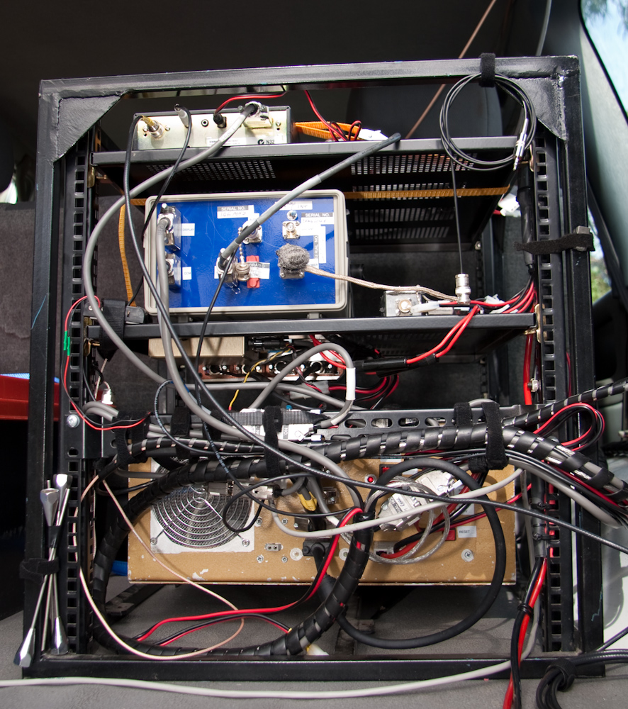
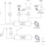
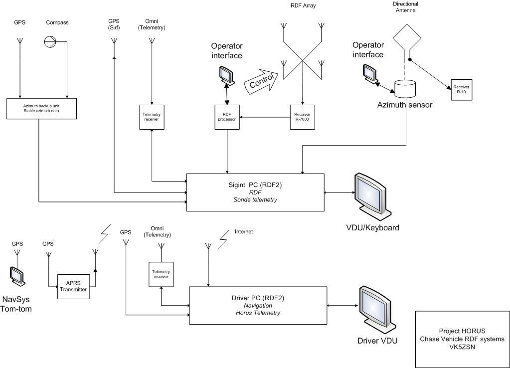
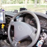
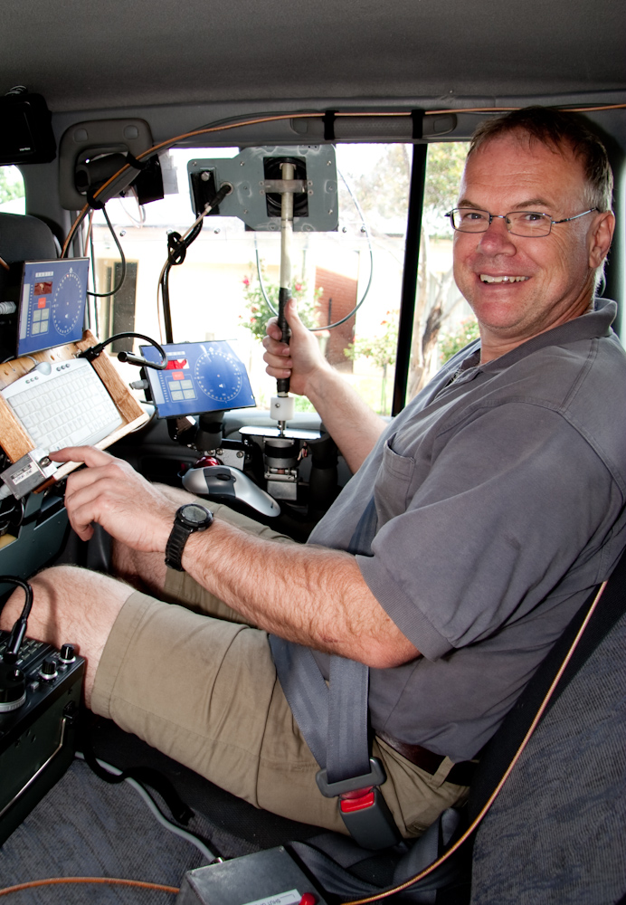
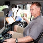
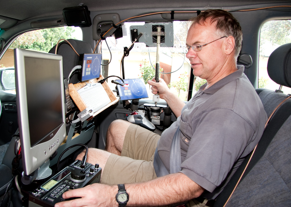
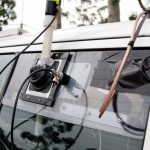
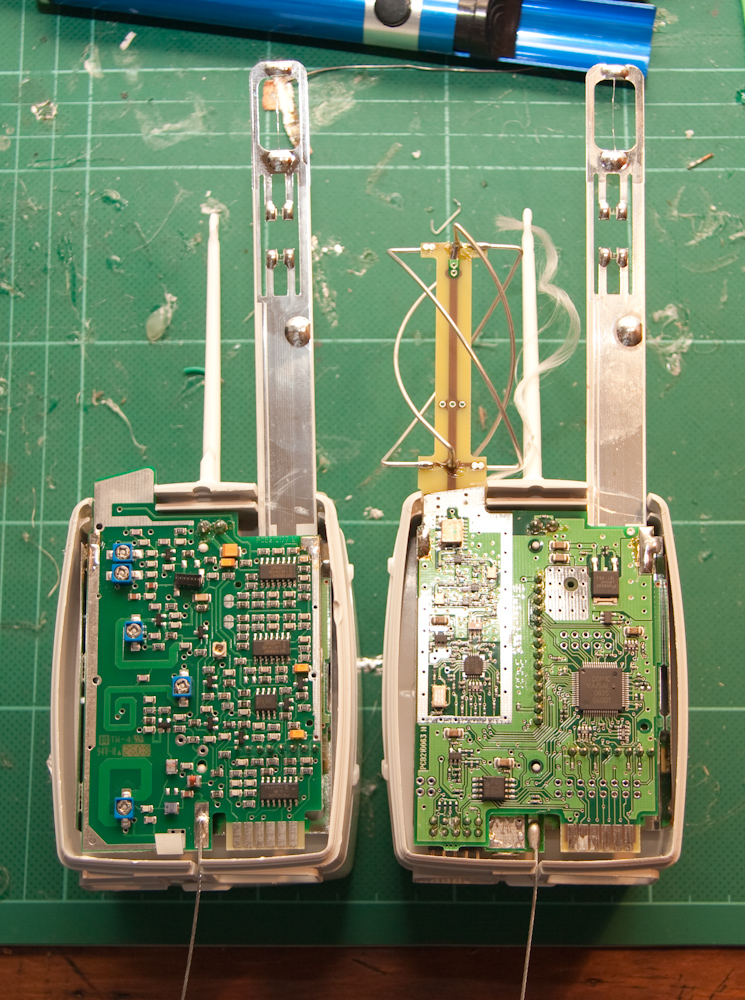
Adrian was also keen to show me his RDF setup - a Toyota Land Cruiser kitted out with an amazing array of radio's, computers & custom electronics that Adrian has put together. At the heart of the setup is Adrian's radio direction finder module - a system that Adrian came up with some time ago, it interfaces with both a rotating beam yagi antenna, and performs Doppler based direction finding. The Doppler array (4 1/4waves on the truck roof) is able to give an instantaneous bearing to a radio source without requiring manual input. The output from the system is plotted to a GPS tracked map, to triangulate the location of the source.

At the controls of Adrians RDF truck
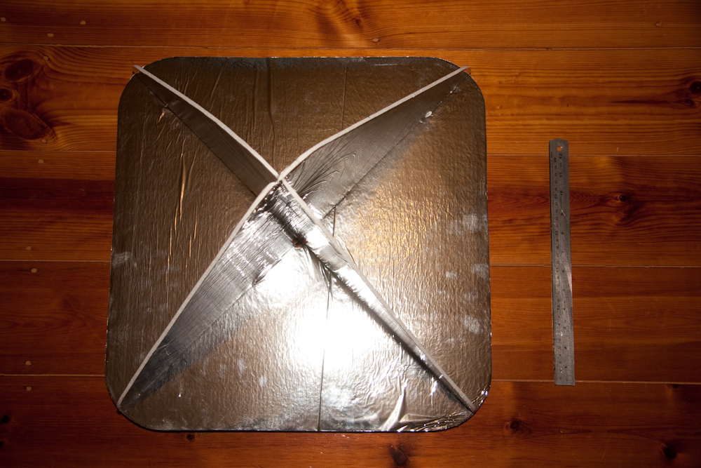
To demonstrate the system, Adrian took me out to chase one of the 2 daily BOM balloons. Predictions run with the CUSF flight predictor suggested that the balloon would land somewhere near Sedan, a manageable distance from Adelaide. Our BOM primarily launches analogue radiosondes (Vaisala RS92K) - these 'sondes do not include GPS receivers, they are tracked by ground based radar. This meant we wouldn't be able to track the Sonde's course by GPS, the only way to locate the 'sonde is via RDF techniques.
We headed out towards Sedan hill, so that we would have a good vantage point & be able to track the 'sonde as it came down. No problems up until this point - I was operating the RDF equipment, after a short while spent learning to work everything, I was confident that we had a good idea of where the balloon was. However, we'd forgotten to start the radiosonde decoding software at the beginning of the flight, and due to the very limited information broadcast by the analogue 'sonde in question, we didn't know if the balloon was still ascending, or if it had started to descend.
A short while after we arrived at Sedan hill, the signal faded, then abruptly disappeared. Unsure if the 'sonde had landed or if it had failed, we set off down the last vector we'd plotted. 10 minutes later, we still hadn't heard the signal, until we passed a field & I heard one of the radios in the truck pick it back up again - but this time on a totally different frequency! It looks as though the bump on inpact had upset the analogue radiosonde's crude transmitter (adjusted with trimpots by the looks of things) & shifted its frequency. A short while & a few vectors later, we were quite confident we'd found it.

The radiosondes position triangulated
A short trek out into a wheat field netted us the radiosonde & radar reflector, and a very burst balloon.

Yours truly with the recovered radiosonde
As well as the analogue radiosonde we recovered, I have in my possession a more sophisticated digital 'sonde that Adrian gave me. Whilst the temperature and humdity sensors these carry are good for a single use only (needing calibration), the pressure sensor still functions perfectly - I powered up the radiosonde & decoded it's output, and it was reporting 14.7 PSI. I'm interested to see if I can extract one of these pressure sensors and interface it with my Arduino flight computer.
I've also started work on a daemon to plot information directly from my telemetry in OziExplorer, giving me the position of my balloon live on a map without needing an internet based service such as Google Maps or Google Earth, as internet access probably won't be available in regional areas. OziExplorer provides a great API that I'm using to do this.
Steve, another balloon enthusiast from RandomSolutions has kindly donated a GPS module which I'm planning to use on a test balloon flight. I'm waiting on my balloons from Kaymont, I suspect shipping may have been delayed given the Christmas rush.
A few more photos of the RDF truck & balloon below:
-
- Adrians RDF truck
-
- Adrians RDF truck
-
- At the controls
-
- Adrians RDF equipment
-
- Adrians RDF truck block diagram
-
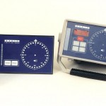
- Adrians RDF unit
-
- Adrians RDF unit
-
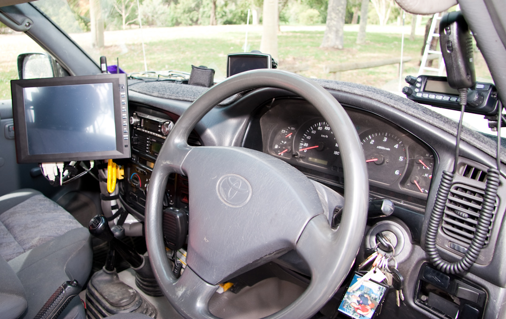
- Drivers seat
-
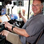
- Adrian manning the contols
-
- Adrian manning the controls
-
- Through-window beam mount
-

- Remnants of the BOM balloon

-
- Radar reflector
-
- BOM radiosonde
-
- Analogue (left) digital (right) sondes
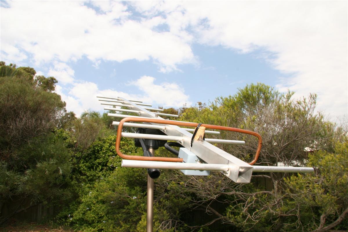
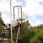
Another radio test a new yagi
I made up 1.3m yagi yesterday - the biggest that'll fit in the boot of my car ![]() . I used K7MEM's excellent yagi designer to come up with a plan, and cut the pieces from aluminum tubing, which I had TIG welded at a local machine shop for $20. My folded dipole is made from a length of copper tubing, but I don't have much faith in it - it was difficult to get it sized correctly. I suspect I may need to swap it for a better one after I do some proper testing on the antenna.
. I used K7MEM's excellent yagi designer to come up with a plan, and cut the pieces from aluminum tubing, which I had TIG welded at a local machine shop for $20. My folded dipole is made from a length of copper tubing, but I don't have much faith in it - it was difficult to get it sized correctly. I suspect I may need to swap it for a better one after I do some proper testing on the antenna.
We tested the radio again last night, using the coat-hanger yagi, and the larger yagi. The coat-hanger yagi was brilliant considering the effort invested, and is much more practical than the large (1.3m) yagi. It's nowhere near as directional as the larger yagi, given the lower number of elements, and is extremely lightweight - so it's super easy to use with 1 hand.
As I found out, two hands are needed for the large yagi, even though it's lightweight (being aluminum). Even using two hands, it's very difficult to keep it exactly on target, and it's extremely directional. I've since made mounted it to the quick release block on my tripod, which should keep it pointing where we want.
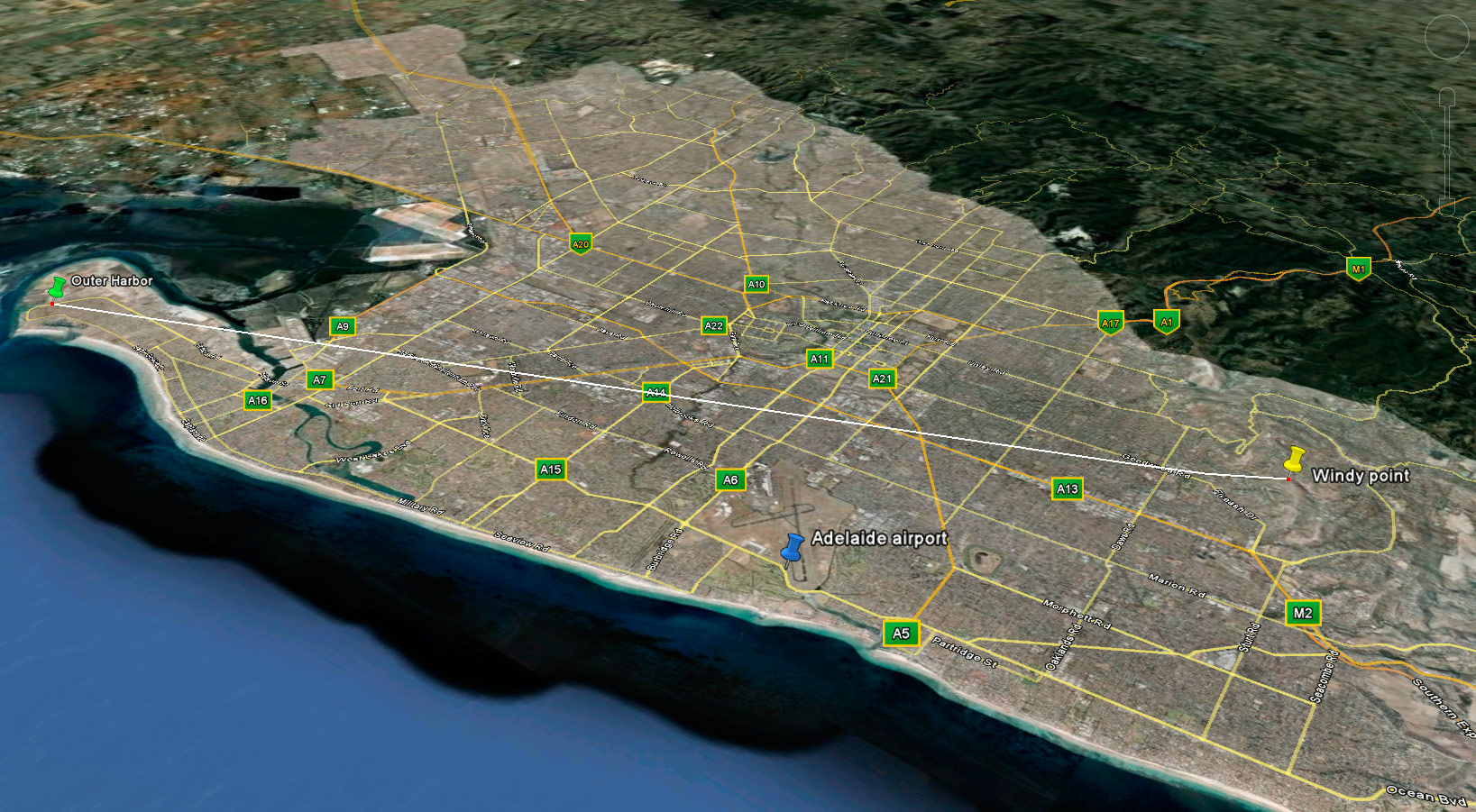
We tested the same distance as previously - from the airport to Belair, as well as going out further with the yagi's. The coat-hanger yagi performed brilliantly at the airport, getting an excellent signal (where the 1/4 wave whip we used last time struggled). Going out further to outer harbor, the coat-hanger yagi was struggling to pickup anything decodeable, but the larger yagi did the trick. Total distance from outer harbor to the transmitter was 27.5km, with a very poor line of sight, and only 300m or so at the transmitter side. Overall quite successful, though I suspect the large yagi is capable of much better performance with some tuning.
-
- Windy point -> Outer harbor
-
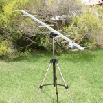
- New yagi mounted on the tripod
-
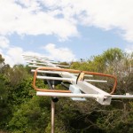
- Horizontally polarized
-
- Vertically polarized
Antennas
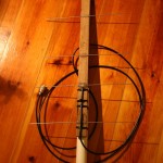
I've been busy reading into Yagi antenna design, and have come up with a few designs for the Yagi's we'll use to track the balloon in flight. I'll be building the antennas from aluminium, to keep weight down. I'm planning on a 1.5m long beam, allowing me 10 elements, and a gain of ~14dBi.
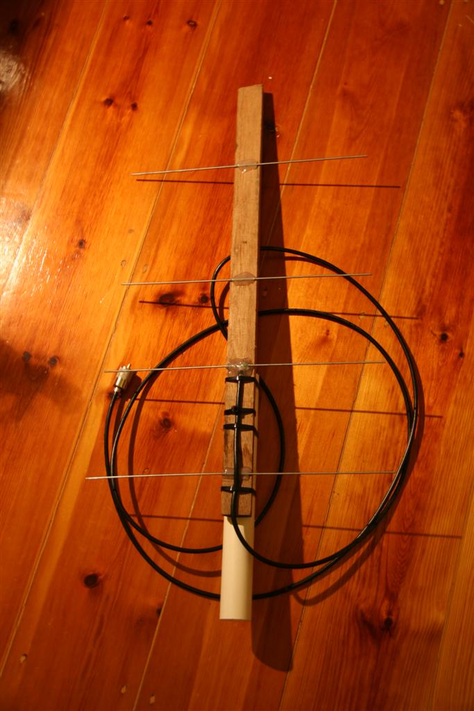
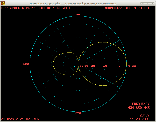
I made up a small 4 element yagi just now, with about $2 of materials - some wood, a few coat hangers, PVC pipe & zip ties. Haven't had a chance to test it properly, but it seems promising. Modeling it in Yagimax suggests a gain of around 9dBi, which is great given the cost & time invested in it. Hopefully will get a chance to make up a long yagi in the next few days as well as test it out.
-
- The 4 element yagi
-
- Modeling the 4 element yagi
Build update
A fair bit of an update - most of the payload is built, most of the code is written.
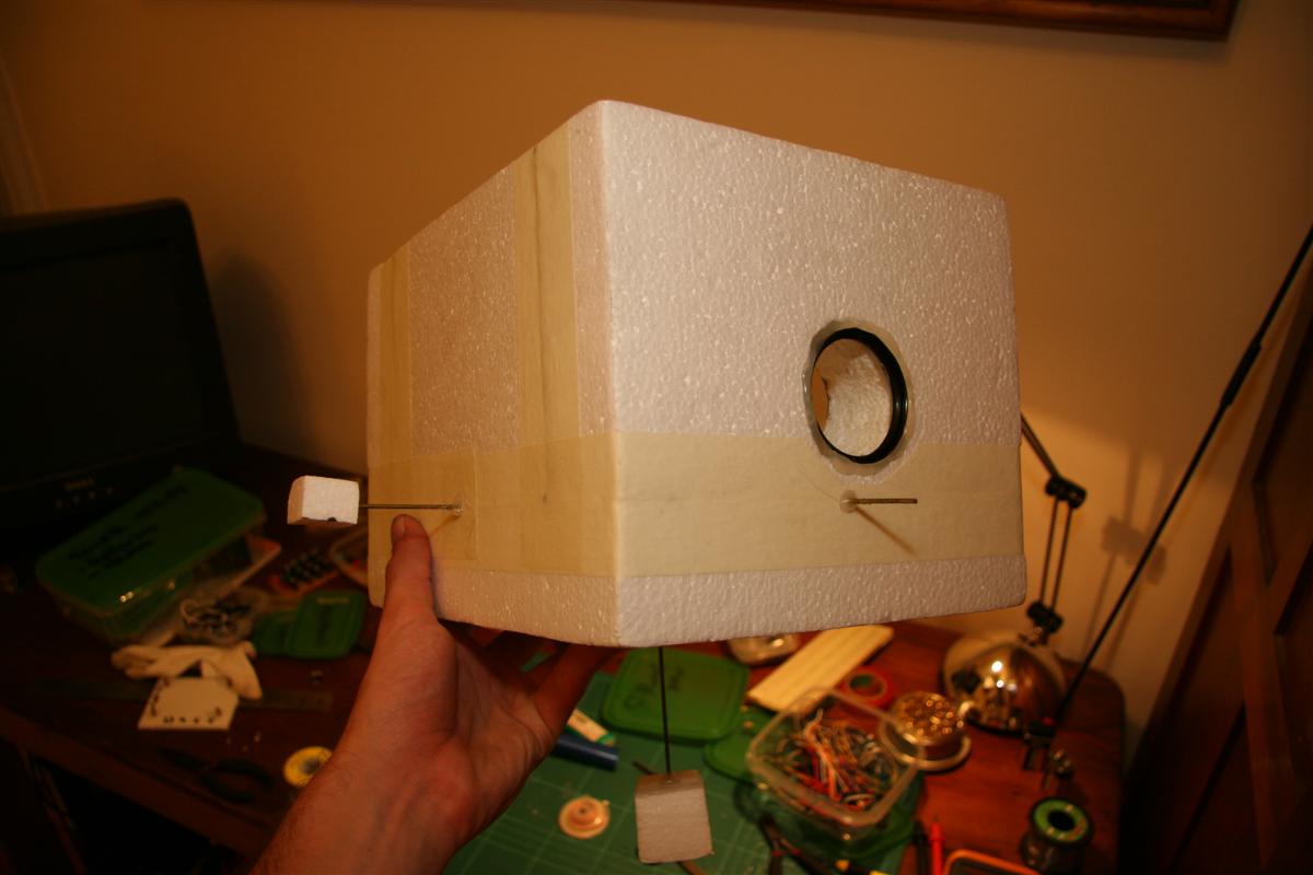
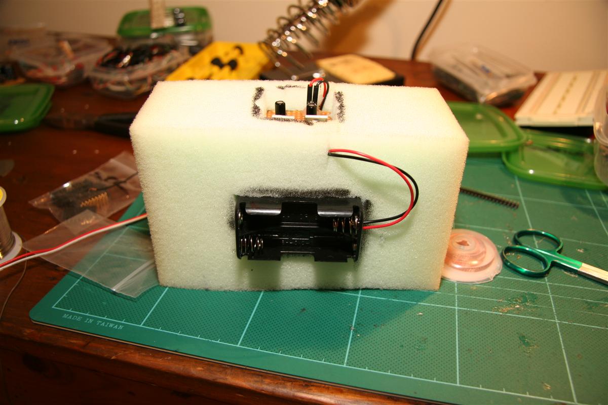
After looking for a suitably sized polystyrene eski/beer cooler for a while & finding almost nothing with the thickness I wanted (25mm+), I gave up and bought a sheet of 50mm polystyrene from a rubber store. I made up a hot wire cutter using some nichrome wire, an old computer power supply and about $10 of wood & steel from my local hardware store, and chopped up what I needed to make a suitably sized box.
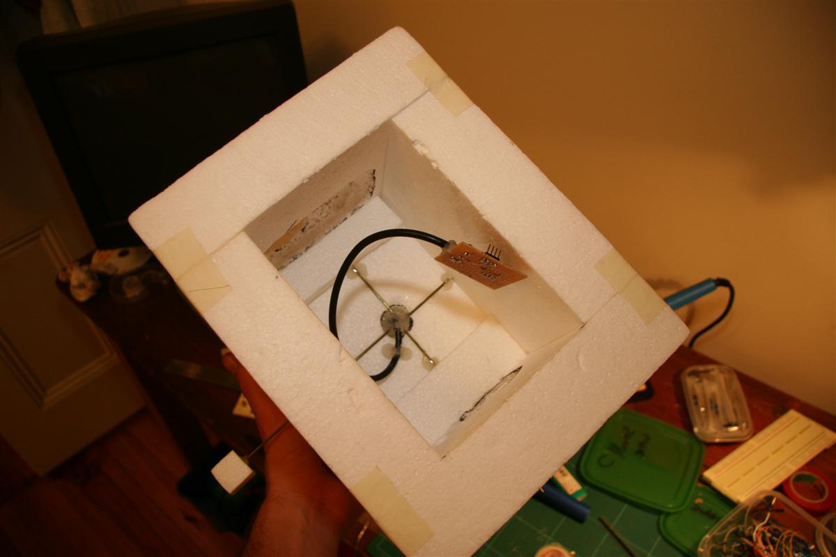
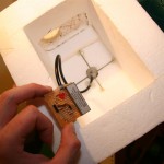
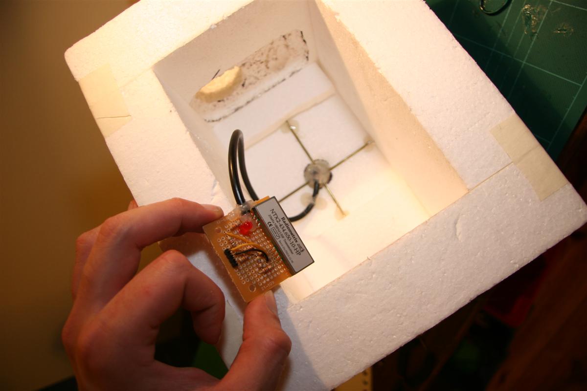
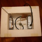
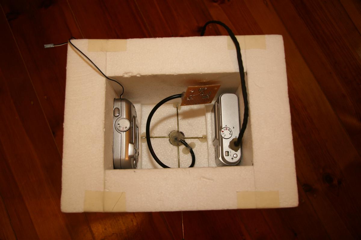
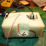
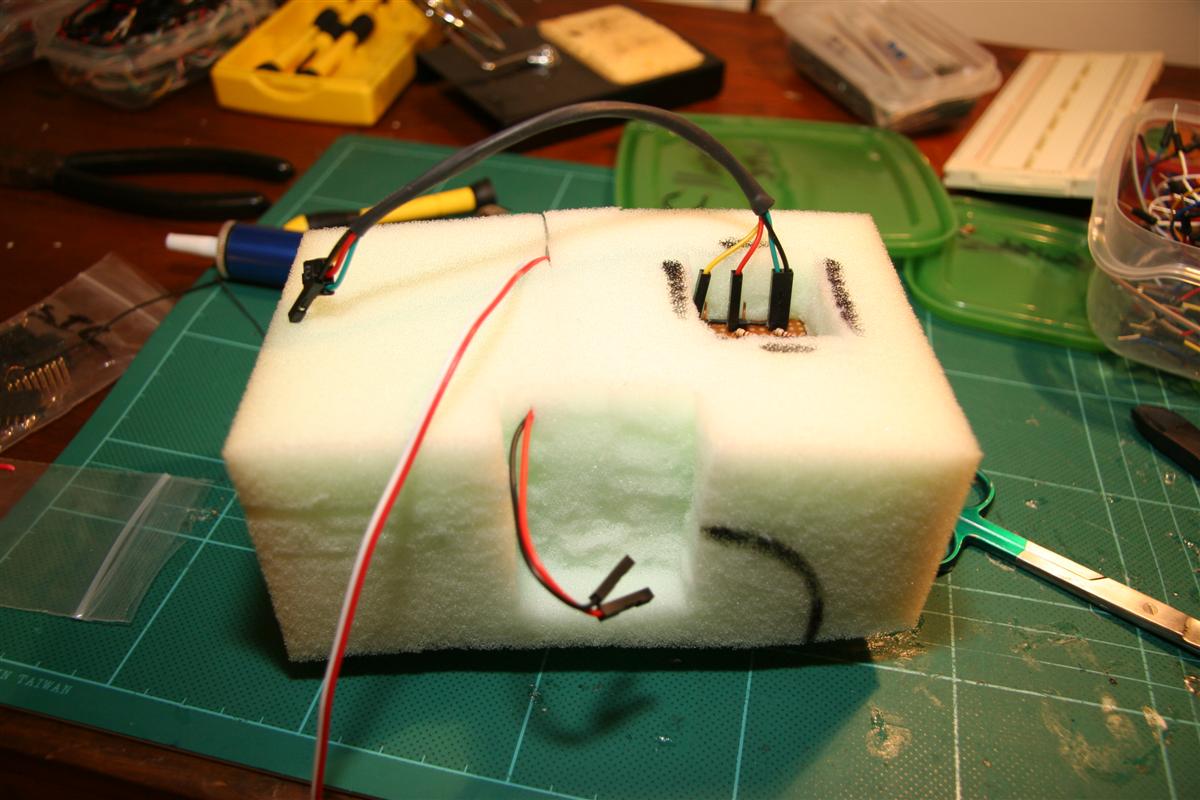
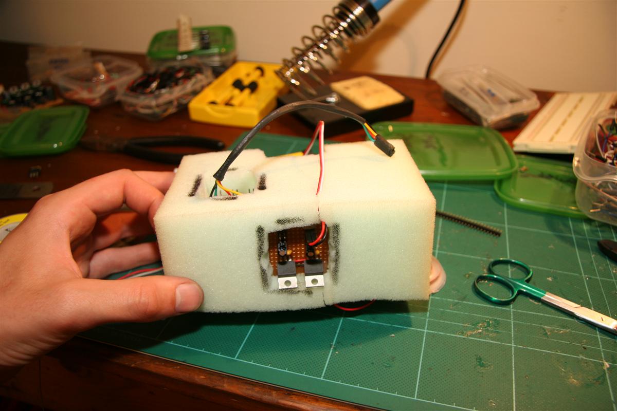
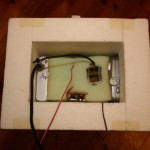
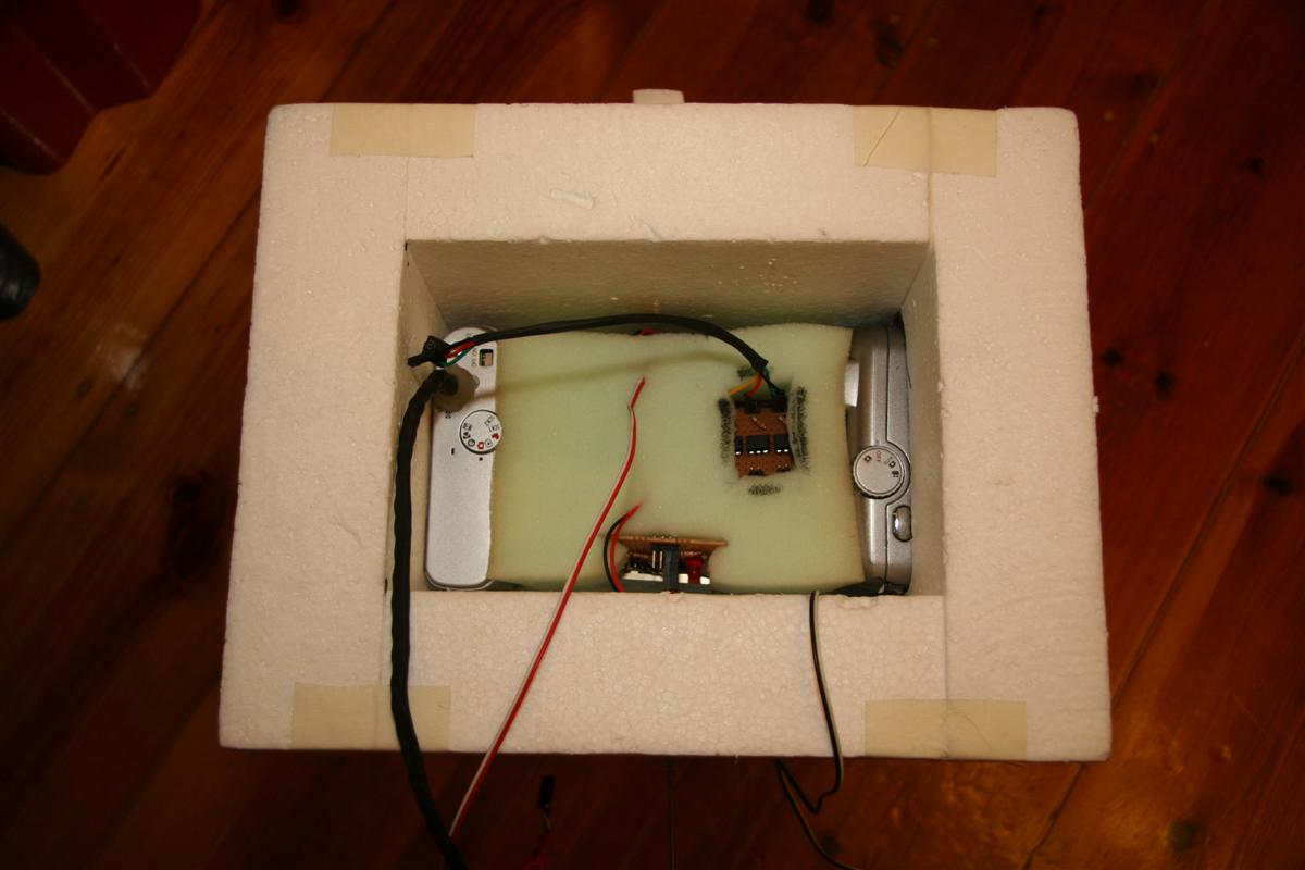
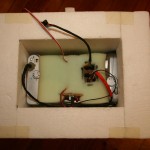
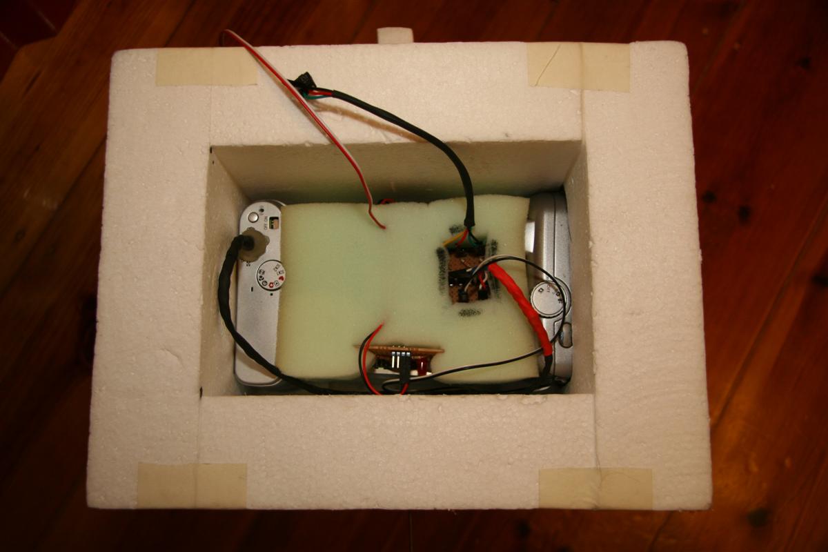
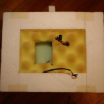
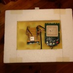
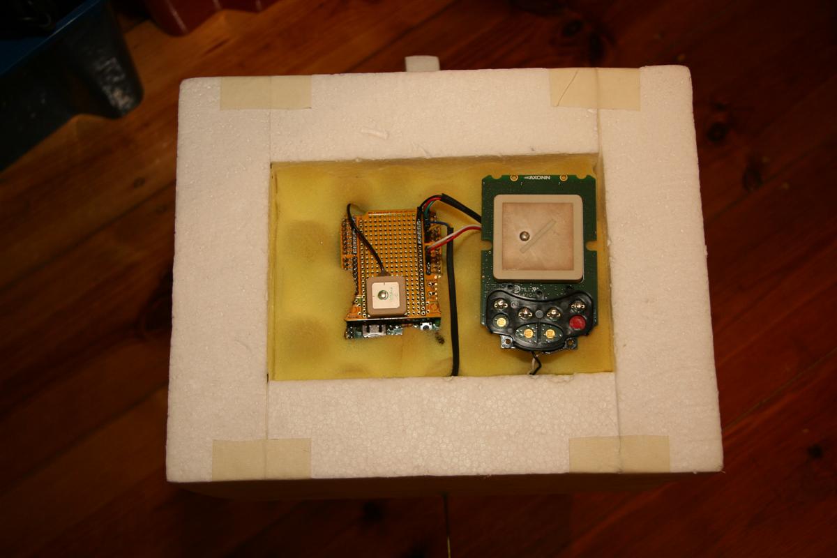
The box is now all cut & joined, with recesses cut for the cameras & antenna installed - the transmit antenna is a 1/4 wave whip with a radial ground plane. Camera lenses are separated from the outside world by UV filters you would use on the end of an SLR lens. I'm quite happy with the way it turned out - the GPS module is up top, next to the (backup) SPOT tracker, both pointing to the sky. Most of the weight is down the bottom, with the cameras & batteries, which should keep things the right way up coming down. All the seperate boards are held in a foam core, keeping everything securely in place.
-
- The payload box
-
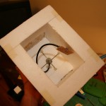
- Inside the payload
-
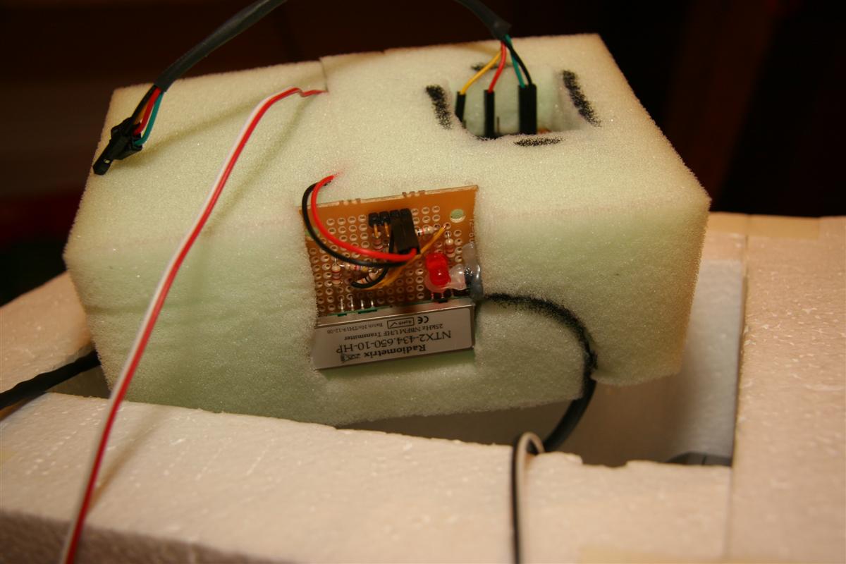
- Radiometrix + RF out
-
- Cameras inserted
-
- Foam core housing power supply, camera triggers
-
- Power supplies (3.3v 5v)
-
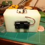
- Battery pack (4x lithium AAs)
- Radiometrix inserted
-
- Foam core in place
-
- Cameras connected to trigger board
-
- Top foam layer inserted
-
- Flight computer SPOT tracker in place
I've got the flight computer logging its data to an SD card, and have been testing it as a regular GPS logger in the car. The Lassen iQ doesn't seem to be the most sensitive of modules, often losing lock between tall buildings and the like, but this won't be an issue in the open sky. My 12mm coin cell holder arrived, meaning I could solder it down and pop in the GPS backup battery - it now takes about 30 seconds to get a GPS lock when the micro is switched on, as opposed to 5-15 minutes without the backup battery.
I've rewritten sections of the GPS code to be more tolerant of failure & also transmit checkum data on transmitted (radio) strings. Still haven't had another go at flashing the arduino's bootloader, for fear of destroying yet another Atmega. ![]()
Gary from Air Liquide in Elizabeth organised a good price on Helium for us - $100 less than BOC wanted for the same cylinder size. I'm skipping on the idea of using a regulator designed for filling balloons, as the flow rate is too low. Adjustable flow rate oxygen welding regulators are slightly more expensive, but we won't be waiting 3 hours for the balloon to fill.
My balloons and chute will be ordered soon - not long now! ![]()
How to kill an Arduino
I was playing around with the Arduino's watchdog timer the other day - ideally, I'd like to use it to reset the flight computer in case it locks up, or my code goes awry somehow & gets stuck in a loop, etc.
The Atmega328 (the core of my Arduino) does implement a watchdog timer - though unfortunately it's not possible to use it with the standard Arduino bootloader - the reason being that if the watchdog resets the chip, it remains enabled, and worse, its timeout reduces to 15ms - which doesn't give the Arduino bootloader long enough to run any code, so the Arduino gets stuck in a reset loop.
Fortunately, ladyada has written a modification to the Arduino bootloader to work around this problem - all I need to do is reflash the Atmega to use the modified bootloader.
Besides buying a dedicated programmer, the easiest (and cheapest) way to do this is by building a parallel port programmer - an old parallel printer cable, a few resistors and a hacked together ICSP header and I was done - at a cost of $0.
Fast forward to a few minutes later, trying to burn the bootloader into the chip - things are not working well, all I am getting is errors.
Eventually I had another look at my wiring to ensure I hadn't made a mistake (though I did triple check everything) and realised what I'd done. In my rush, I had not read the pin numbers on the parallel cable - I'd based my pinout at looking at the male end of the cable, wheras the diagram I was following was using the female (host) end. So while my leftmost pin was #1, it was #13 in the diagram.
I undid my wiring, and rewired everything up correctly, then tried to reflash to chip - but too late, I'd already toasted it with my first attempts! It no longer runs, and I can't upload any new code to it, so I've ordered a couple of new Atmega328's (they're cheap, thankfully!) which should arrive soon.
I've also been running a few predications with the CUSF flightplan predictor and trying to pick an appropriate launch spot. Whilst I've previously found that winds tend to blow west -> east here, current predications are rather variable, with the possibility east -> west winds (which would land us in the ocean) quite high. It looks like we might need to move further inland for the launch, and keep an eye on the forecasts. I'll also be writing an automatic cutdown system to cut the payload down if it looks like it might drift over populated areas or the ocean.
Deliveries, code more
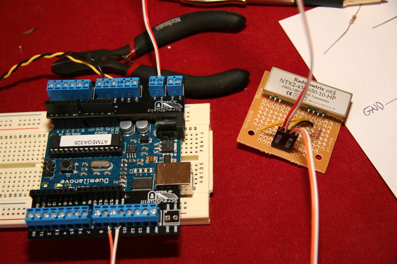
Yesterday saw a few packages arrive. My Radiometrix NTX2 came, as did the primary camera and a bunch of heatshrink I'd ordered off ebay.
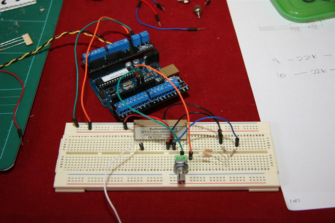
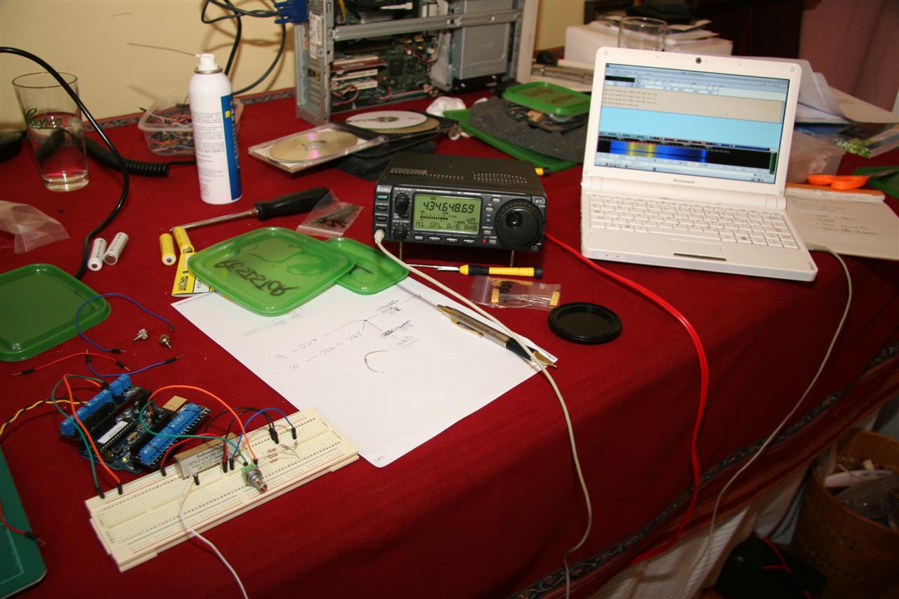
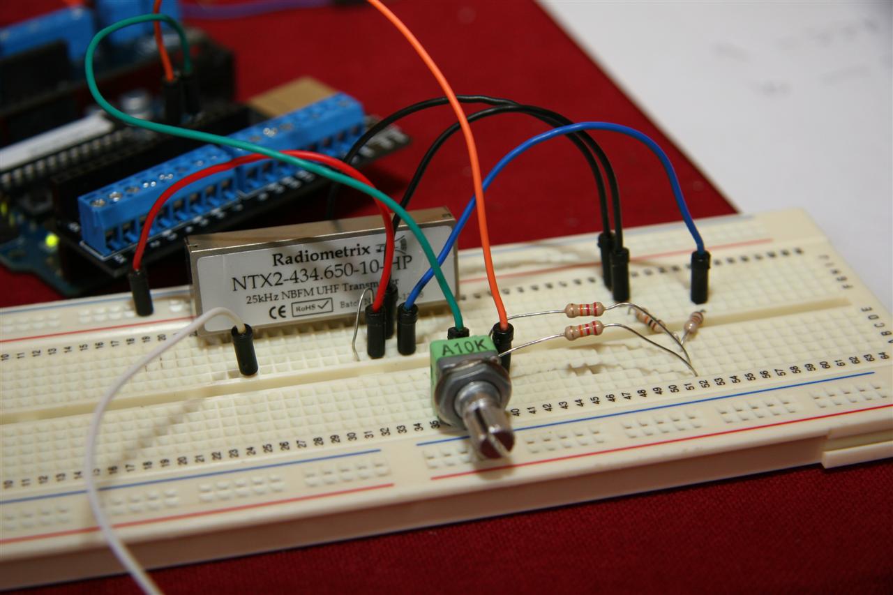
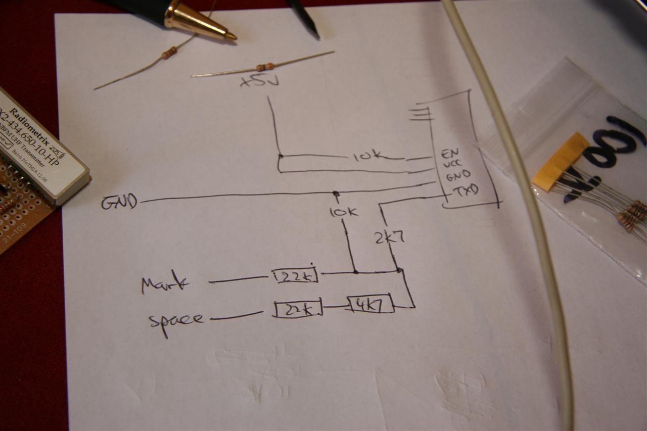
I had a mess around with the NTX2 & potential dividers, & after much tweaking came up with a solution that worked. Testing code on the other hand was problematic - eventually with some help from fergusnoble over at #highaltitude on freenode, I realised that the delayMicroSeconds() call wasn't working with a value as large as 20,000 (20ms = 1/50th sec) - a few adjustments later, and transmission was working perfectly, so I built up the module on a board.В So far I haven't tested with any antennas, but it seems to cover the distance across the room just fine.
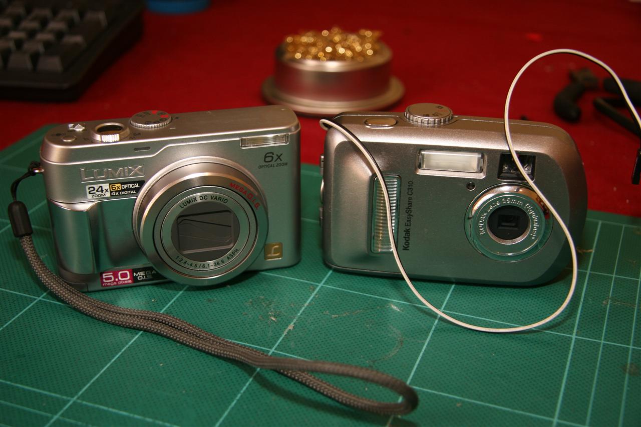
The camera seems great - and the seller was good enough to give me a discount due to the delay in shipping! External triggering will likely by more tricky than the Kodak, given that it has a half-press button for focusing, which the Kodak does not.
I've also written most of the code to handle the GPS side of things, which I'll post shortly.